

Overview
The HDROB is a modular and freely programmable system, to be used as a steering platform for ASIC and discrete electronics development.
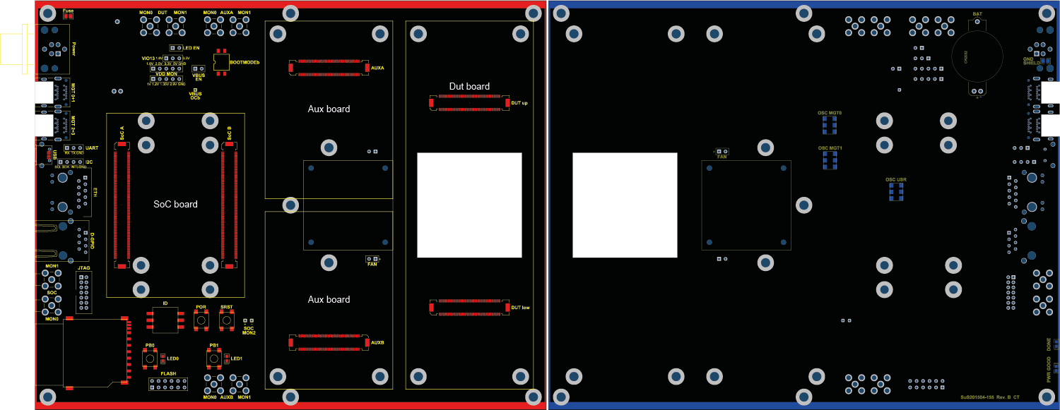
The base board is the lowest part in the board stack. Its outline dimensions are 200mm x 160mm, thus a double-size Eurocard. The card can be mounted into an enclosure by sliding the long edges into mounting rails, or by using the seven mounting holes. All user connections are accessible on the left handed short side.
Besides being the mechanical support, the baseboard routes all the electrical connections between the add-on connectors, user and bring-up connectors.
Download PDF drawings: HDROB top HDROB bot
The SoC board holds most of the active components. The HDROB system is designed for Xilinx-based Enclustra SoC modules, but can also be fitted with plain FPGA modules.
Up to two Aux boards can be attached to the baseboard, to provide reusable hardware add-ons. A large number of analog, single-ended and differential digital lines as well as power supply connections are routed towards the SoC and the Dut board.
Forseen use cases for Aux boards are high-voltage generation for biasing of photon detectors, bipolar high-current supply for a Peltier cooler and signal conditioning for precise board-to-board clock synchronization.
The integrated or discrete device under test is mounted on the Dut board, which mounts to two connectors on the right-hand side of the base board. This board is connected via numerous lines to the SoC and the two Aux boards, as well as to different power buses and control lines.
The base board is cut out on the center of the Dut board, allowing to mount a heat sink or to irradiate the device also from the bottom side.
Mechanical details
All dimensions in mm.
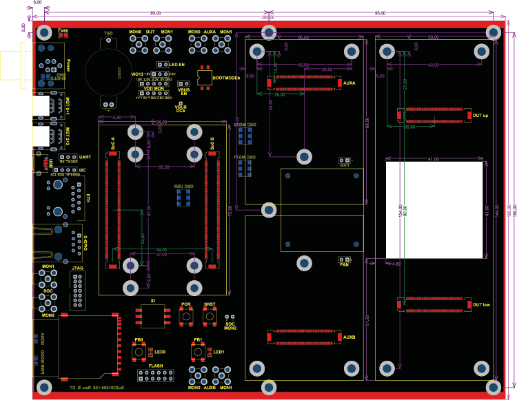
Download dimensioning: HDROB dimensioning
- PDF with dimensioning
- Connector stack height options
Base board
- Dimension: Outline, thickness
- Mounting holes: Position, diameter
- Mounting in a slotted case
- Reserved space for SoC module
SoC board
Aux board
- Dimension: Outline, thickness
- Mounting holes: Position, diameter
Dut board
- Dimension: Outline, thickness, heat sink position
- Mounting holes: Position, diameter
Electric details
- Shared VDD/GND buses
- Shared I2C bus
- Impedance of single-ended/differential traces
- Maximum current rating for FX10 sockets: 0.3A per pin, maximum voltage rating?
Base board
- Digital monitor outputs (SMA) for SoC board
SoC board
Aux board
- Single ended+differential wires to the SoC board
- Single ended+differential wires to the Dut board
- Analog (plain-wire) lines to the Dut board, may be used for powering
- Analog (plain-wire) monitor outputs (SMA)
Dut board
- Single ended+differential wires to the SoC boar
- Single ended+differential wires to the Aux boards
- Analog (plain-wire) lines to the Aux boards, may be used for powering
- Analog (plain-wire) monitor outputs (SMA)